


What is a fault condition?

A fault condition in an electrical system occurs when there’s an unintended path for current to flow, typically due to a short circuit between conductors or between a conductor and ground.
This can happen due to various reasons, including:
- Short circuits:
Direct contact between live wires or between a live wire and ground.
- Lightning strikes:
Can induce high currents into electrical systems.
- Animal contact:
Animals bridging connections.
- Corrosion or physical damage:
Degradation of insulation or connections.
- Human error:
Accidental contact or incorrect wiring.
How does a fault current differ from normal current?
Normal AC current flows in a circuit as designed, with a specific voltage and current level. In contrast, a fault current is an abnormally high current caused by the low impedance path created during a fault. This high current can lead to:
- Overheating:
The high current can cause wires and equipment to overheat, potentially leading to fires or damage.
- Mechanical stress:
The electromagnetic forces created by high currents can cause conductors to move or even rupture.
- Arc flash:
If a fault current arcs across an air gap, it can create an extremely hot and dangerous arc flash, potentially causing serious injuries or death. Understanding fault currents is crucial for electrical safety of all involved directly or indirectly as well as those in close proximity to the system.
- Electrical safety: Proper calculations and safety measures can prevent accidents, injuries, and damage to equipment.
- Equipment protection: Selecting the right protective devices, like circuit breakers and fuses, is essential to interrupt fault currents before they cause damage.
- System reliability: Accurate fault current calculations help ensure the stability and reliability of electrical systems.
How is fault current calculated?
Fault current calculations are typically based on Ohm’s law (I = V/R), where:
- I: is the current in amps.
- V: is the voltage in volts.
- R: is the resistance in ohms.
During a fault, the resistance is significantly lower than normal, leading to a high fault current.
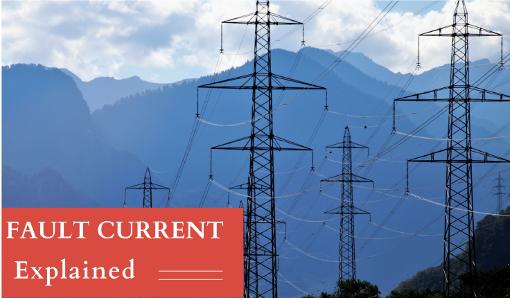
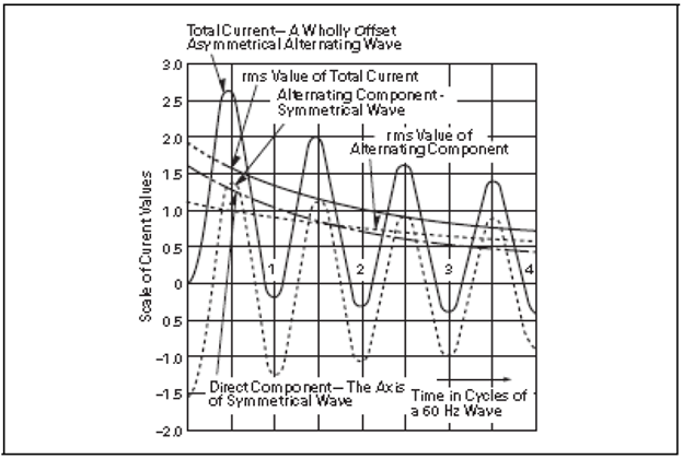
An AC fault results in the heavy flow of alternating current available from an electrical source during abnormal conditions. This current can be induced onto a structure without any metallic connection to it, such as in the case of pipelines in a common corridor with power lines. Current can also flow via conduction in grounding conductors, the soil, or other unintended paths back to the source, affecting cathodically protected structures.
Different applications are subject to varying levels of AC fault current, but in all cases, this value of phase-to-ground AC fault current must be determined, even if only estimated. Some applications may not have notable AC fault current exposure so the lowest standard product fault rating may be chosen. A high fault current capacity does not necessarily result in higher reliability and “Bigger may not be better”. Factors that affect reliability are typically surge protection from lightning and earth potential rise and the ability of the equipment to recover sufficiently from heat generated under stress conditions.
Below an example of an Insulating joint is discussed, however other CP applications are listed that are discussed separately along with fault current determination methods elsewhere.
AC Fault Current by Application when deployed in a Cathodic Protection setting.
- Insulated Joint/Flange
- AC Voltage Mitigation on Pipelines
- Electrically powered flow meters etc.
- Decoupling utility ground from distribution/ user transformer ground
- Lead sheathed power cables
- Insulated Joint Protection
Insulated Joint Protection
Insulated joints are usually deployed where pipelines leave a pumping facility, off take connections to a secondary discharge point from a main supply pipeline or entering a reservoir or some form of pumped product discharge facility. The insulated joints are used to electrically isolate the pipeline/structure from the grounded pumping equipment or reservoir to maintain and preserve Cathodic Protection currents applied to mitigate corrosion of the pipeline. As the insulated joints are not usually directly tied via a direct electrical connection to an AC source, the possible fault current is usually low to moderate and forms a secondary protection mechanism to the pumping equipment or receiving equipment’s protection circuit breakers.
Higher exposure exists for insulated joints on pipelines serving cooling fluids to fluid cooled transformers or HVAC equipment, or where the pipeline may upon fault condition, form the metallic electrical return path for fault current to the source of the current.
Calculation method:
- For insulated joints in a common corridor with power lines,If an AC mitigation study is being performed, the mitigation consultant can advise the expected or modeled fault current level.
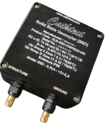
- For common corridors with power lines with no calculations or little to no available data, typical values obtained through experience and general industry preference indicate a reasonable decoupler fault withstand would be 3.7kA.
- Typically, the utility supplier may be approached to verify the protection rupturing curve revealing both the kA rating and duration until isolation (time taken by the protection device to disconnect the current source from the overhead powerline).
- The industry standard internationally specifies a 30 cycle duration (0.02 seconds for 50Hz and 0.016 seconds for 60Hz).
- Familiarizing oneself with the latest AMPP Guideline will inform on overhead line support configuration and tower differences and how they relate to ground induction patterns.
- For cases where high fault currents are expected due to close proximity or other factors such as a cooling fluid pipeline on a HVAC transformer, select a higher product rating as appropriate. This information will be available from the equipment manufacturer along with the protection breaker rupturing time curve.
- For sites not in a common corridor with power lines, and not in metallic contact with AC fault sources, product ratings lower than 3.7kA may be chosen. In a typical discharge pumping application, a device as low as 1.2kA could be utilized upon confirmation from the plant Electrical Engineer.
For more information on AC mitigation solutions contact [email protected] for expert advice, innovative products and Cathodic Protection support.